|
Assembly of Plane
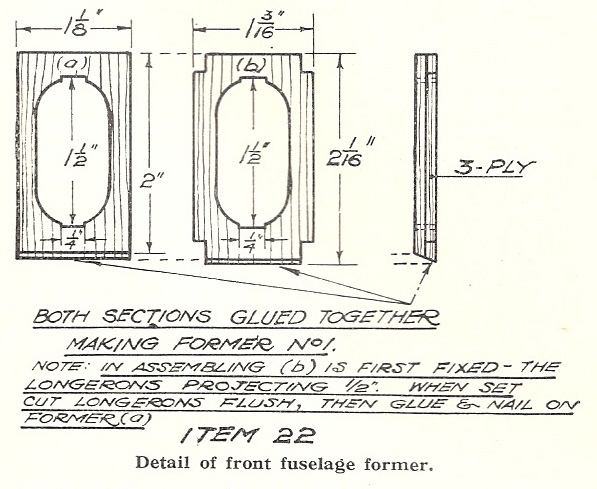
Thread on centre section ribs first, followed by camber and nose ribs. One side of the wing is assembled at a time. It must be built up on a perfectly flat table or board, otherwise a permanent twist in the wing may result, which can only with great difficulty be got out after the glue is set. Thread ribs on spar one side to approximately correct position, placing leading and trailing edges on table 6 in. apart. Warm glue, and run a little round all four sides of main spar at pencil marks, also in notches on ribs except at centre ribs, which are fixed last. Push ribs into position on spar, then lay on board, and with assistance push leading and trailing edges in place. Lay two weights about 1/2 lb. on the structure, one near the centre and the other about 4 in. from tip. Prop leading and trailing edges on opposite sides up, or they will droop, and may get are square both vertically and fore and aft, then leave to dry for at least six hours. Glue is quite sufficient to hold the framework together, and ribs need not fit too tightly on spar. When dry, perform a similar operation on opposite side, then fix wing tips by glueing and nailing them on with 1/4 in. pins. One can either steam bend wing tips, or for that small curvature they may be bent cold. Finally, glue in position centre ribs, the ends just covering notches in leading and trailing edges, also the packing piece under the leading edge between centre ribs. When dry, with file and glass paper, round leading and trailing edges, also wing tip, and make slight radii at corners as shown in plan. Tail Plane. Item No. 24. This component really combines both tail plane and elevators. It is of 16 s. w.g. piano wire, bent to shape, bound and soldered, the binding being done with very fine tinned iron wire. Set tailplane out in plan, and cut wire to correct length, plus about 1 in. for any slight error. Round 16 s.w.g. wire at centre solder a piece of fine tinned binding wire. Two rounds will do, to mark centre, and this point should coincide with the centre line on setting out board when making up tailplane. With round nose pliers bend component to shape, and note that wires do not cross, but meet for 3/8 in. at centre. True up, and bend wire so that it lays flat, then lightly solder at the three points shown in item 24. Bind tightly with binding wire, and re-solder. In very light work, say with 20 s.w.g , piano wire, soldering alone is sufficient, but in using 18, 16 and 14 gauge wire binding, then re-soldering, is advisable. Remember, the projecting prongs are fixed to the top side of tailplane, and pass through two screweyes, item No. 19, at rear of fuselage. |
Rudder. Item No. 14.
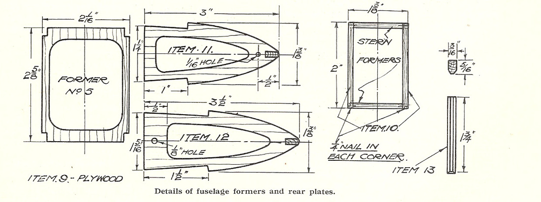
This component is built up in a similar manner to the tailplane, though with two pieces of 16 s.w.g. piano. wire. The bottom portion also forms the tail skid, and adjusting hook in front. Some may prefer to make the hook separate, as 'illustrated. The little skid bracket is fixed to the bottom stern former by a I0 B.A. bolt and nut, item No. 21. Nose Piece. Cut block to size and mark centre line down its length both sides. Follow this by making lines parallel 1/8 in. away, giving a total width of 1/4 in., the width of the spindle bearings. Mark position of spindle holes, and drill slightly oversize holes for clearance. Mark radii top and bottom, and with chisel pare to shape. Now pare the radii on the sides. It is best to do it this way, for the chisel may slip if you do the sides first. Make up spindle bearing plates, spindles, etc., and assemble temporarily to make sure that gears run free and spindles are in correct alignment. Size of drill for top spindle 14 s.w.g. is No. 46 or 5/64ths in. For bottom spindle 16 s.w.g No. 51 or I/I6th in. If drills of that size are not available, diamond pointed drills can easily be made up from odd lengths of piano wire, and tempered. Cut the little recesses on rear face of nose block square and true, so that the feet of the rear bearing plate do not get distorted when tightening up bolts. Well clean spindles, and tin holes in gear
wheels, before soldering them up. A good radius of solder either side of gear wheels is advisable, for the joint is very heavily stressed by the rubber motor when wound up. 'CLICK' on picture below to enlarge it. |


